Home
› Logic Gates Logic Diagram Symbols / 14.6 mil Me gusta, 60 comentarios - CIRCUITMIX (@circuitmix) en Instagram: " ️ Logic Gates ... - A logic gate is considered as a device that has the ability to produce one output level with the combinations of input levels.
Logic Gates Logic Diagram Symbols / 14.6 mil Me gusta, 60 comentarios - CIRCUITMIX (@circuitmix) en Instagram: " ️ Logic Gates ... - A logic gate is considered as a device that has the ability to produce one output level with the combinations of input levels.
Logic Gates Logic Diagram Symbols / 14.6 mil Me gusta, 60 comentarios - CIRCUITMIX (@circuitmix) en Instagram: " ️ Logic Gates ... - A logic gate is considered as a device that has the ability to produce one output level with the combinations of input levels.. For any digital system, it acts as an elemental building block and is able to make logical decisions. Logic diagrams have many uses. It is an electronic circuit having one or more than one input and only one output. In electronics, a logic gate is an idealized or physical device implementing a boolean function; When both the inputs applied are of 0 volts both the transistors q1 and q2 are off.
Not gates or inverters have a single bit input and a single bit of output. Logic gates are very important and they serve as the building blocks to digital logic circuits using combinational logic. By operating on a number of. Each animated diagram shows the input and output conditions for one of the seven logic functions in. And gate plc ladder logic diagram:
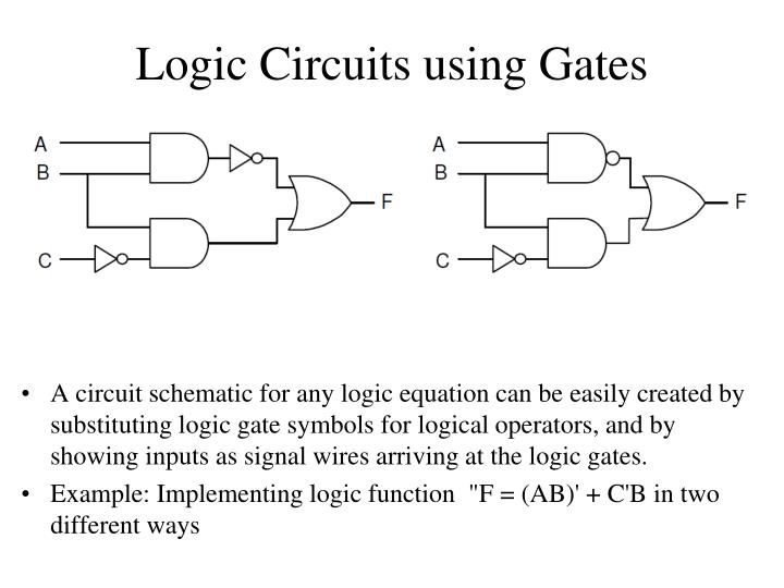
Computer Science from www.multiwingspan.co.uk Timing diagrams also show relationships between input and output conditions in a logic circuit. The logic circuit diagram for this exclusive gate is designed in the combination of and and or gate at the output. Logic gates symbol there are seven basic logic gates: Logic gates definitions, types, symbols and truth tables are discussed. The picture below is a logic gate. Normally the positive supply voltage +vs represents true and 0v represents false. Not gates or inverters have a single bit input and a single bit of output. It can also be done using nor logic gates in the same way.
Normally the positive supply voltage +vs represents true and 0v represents false.
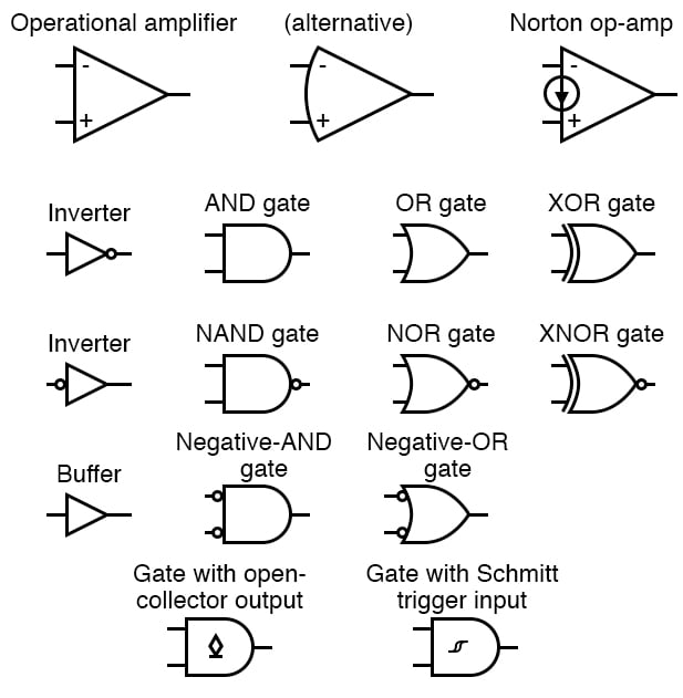
Logic gates as switching circuits. A logic gate is an idealized model of computation or physical electronic device implementing a boolean function, a logical operation performed on one or more binary inputs that produces a single binary. Normally the positive supply voltage +vs represents true and 0v represents false. The and gate is so named because, if 0 is called false and 1 is called true, the gate acts in the same way as the logical and operator. That is, it performs a logical operation on one or more logical inputs, and produces a single logical the following table lists some logic gate diagram electrical symbols in our electrical diagram software. Logic gates are symbols that can directly replace an expression in boolean arithmetic. Logic circuit diagram of nor gate. Logic gates are very important and they serve as the building blocks to digital logic circuits using combinational logic. And, or, xor, not, nand, nor, and xnor. The logic diagram consists of gates and symbols that can directly replace an expression in boolean arithmetic. What is meant by logic gate? The or gate performs the logical (inclusive) disjunction (true output for any true input) the output of or gate is logic high when one or more than one of its inputs is logic high. A logic gate can be represented by a block diagram as shown in figure.
Logic shapes like and gate, or gate, not gate and more are included here. Logic gates are the digital circuits capable of performing a particular logic function. Logic gates definitions, types, symbols and truth tables are discussed. When both the inputs applied are of 0 volts both the transistors q1 and q2 are off. It has n input (n >= 2) and one output.
PPT - Introduction to Electronic Circuits PowerPoint Presentation - ID:226760 from image.slideserve.com Different types of ladder logic diagram that perform different logic gate functions. For any digital system, it acts as an elemental building block and is able to make logical decisions. That is, it performs a logical operation on one or more logical inputs, and produces a single logical the following table lists some logic gate diagram electrical symbols in our electrical diagram software. A logic gate can be represented by a block diagram as shown in figure. Logic gates using the programmable logic controller (plc) is the basic thing you must learn if you want to enhance your electrical and electronics skills. A logic gate is an idealized model of computation or physical electronic device implementing a boolean function, a logical operation performed on one or more binary inputs that produces a single binary. In this post on study of logic gates, you will be getting to know complete details on logic gates (electric gates), logic gate symbols, logic diagram and truth tables. It can also be done using nor logic gates in the same way.
The logic diagram consists of gates and symbols that can directly replace an expression in boolean arithmetic.
The diagrams below show two ways that the nand logic gate can be configured to produce a not gate. Logic 1 represents high, and logic 0 represents low. The logic diagram consists of gates and symbols that can directly replace an expression in boolean arithmetic. (click on the following equations to draw their logic gates diagrams). A logic gate is a small transistor circuit, basically a type of amplifier, which is implemented in different forms the letters are then linked by a boolean symbol indicating the logical action of the gate. As you can see two normally open type contacts are used. Pin numbering starts there and. In this post on study of logic gates, you will be getting to know complete details on logic gates (electric gates), logic gate symbols, logic diagram and truth tables. Each animated diagram shows the input and output conditions for one of the seven logic functions in. Logic gates as switching circuits. In electronics, a logic gate is an idealized or physical device implementing a boolean function; Note that logic gates are not always required because simple logic functions can be performed with switches or diodes, for example Logic gates are very important and they serve as the building blocks to digital logic circuits using combinational logic.
In this post on study of logic gates, you will be getting to know complete details on logic gates (electric gates), logic gate symbols, logic diagram and truth tables. The logic diagram consists of gates and symbols that can directly replace an expression in boolean arithmetic. Pin numbering starts there and. You have the amplifier symbol and then the zero here which is the not operation. Each animated diagram shows the input and output conditions for one of the seven logic functions in.
Integrated Circuits | Circuit Schematic Symbols | Electronics Textbook from www.allaboutcircuits.com As you can see two normally open type contacts are used. Notice how each gate connects the variables together just like the logic blocks in the code above. A logic gate is a small transistor circuit, basically a type of amplifier, which is implemented in different forms the letters are then linked by a boolean symbol indicating the logical action of the gate. In electronics, a logic gate is an idealized or physical device implementing a boolean function; Most logic gates take an input of two binary values, and output a single value of a 1 or 0. (click on the following equations to draw their logic gates diagrams). Logic gates using the programmable logic controller (plc) is the basic thing you must learn if you want to enhance your electrical and electronics skills. The and gate is so named because, if 0 is called false and 1 is called true, the gate acts in the same way as the logical and operator.
Each animated diagram shows the input and output conditions for one of the seven logic functions in.
In this post on study of logic gates, you will be getting to know complete details on logic gates (electric gates), logic gate symbols, logic diagram and truth tables. Logic diagrams have many uses. Logic gates definitions, types, symbols and truth tables are discussed. Basically, there are seven types of logic gates as below. A logic gate is a device that can perform one or all of the boolean logic operations and, nand, nor, not, or, xnor, and xor. All images should be svg. It has one or more input symbols for logic gates. Different types of ladder logic diagram that perform different logic gate functions. This page is a directory for matching symbols for logic gates. Timing diagrams also show relationships between input and output conditions in a logic circuit. Logic gates are basically electronic circuits that perform logical functions such as addition, subtraction, multiplication etc. Video lectures created by tim feiegenbaum at north seattle community college. The logic circuit diagram for this exclusive gate is designed in the combination of and and or gate at the output.