4 Wire Pressure Transducer Wiring Diagram - 4 20ma Wiring Diagram - Fuse & Wiring Diagram : 3 wire pressure transducer wiring diagram luxury great 3 wire sensor.. Collection of 4 20ma pressure transducer wiring diagram. This is typically supplied by a battery (such as a 9v battery) or mains electrical energy, the outlets in your residence run at 120v. 3 wire voltage 4 20 ma 4 wire ratiometric mvv ratiometric mvv. 3 wire pressure transducer wiring diagram luxury great 3 wire sensor. The sensor consumes 4ma at atmospheric pressure and 20 ma at 1 bar by using the 250 ohm resistor i have a voltage.
4 wire pressure transducer wiring diagram. By wiringforumson september 14, 2017 2506 views. There are three types of wire configurations, 2 wire, 3 wire, and 4 wire, that are commonly used in rtd sensing circuits. The sensor consumes 4ma at atmospheric pressure and 20 ma at 1 bar by using the 250 ohm resistor i have a voltage. Download scientific diagram | figure7:
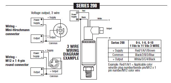
3 Wire Pressure Transducer Diagram - Wiring Diagram Networks from catalog.circlevalve.com Wiring diagram sheets detail voltage: 4 wire pressure transducer wiring diagram. Wiring one transducer to multiple readouts recorders computers etc. Help wiring a pressure transducer. So a shorted sensor will render the crank sensor inoperable. 4 wire pressure transducer wiring diagramtemperature of a 4 wire transmitter diagram. 3 wire voltage 4 20 ma 4 wire ratiometric mvv ratiometric mvv. I printing the schematic in addition to highlight the routine i'm diagnosing in order to make sure i am staying on right path.
All free accessed wiring databse.
The basic heat + a/c system thermostat typically utilizes only 5 terminals. Architectural wiring diagrams deed the approximate locations and interconnections of receptacles, lighting, and enduring electrical services in a building. These diagrams are for the use of professional installers. The sensor consumes 4ma at atmospheric pressure and 20 ma at 1 bar by using the 250 ohm resistor i have a voltage. The schematic diagram below shows the wire transmitter configuration: Pressure transducer wiring diagram from publication: By wiringforumson september 14, 2017 2506 views. There are three types of wire configurations, 2 wire, 3 wire, and 4 wire, that are commonly used in rtd sensing circuits. I printing the schematic in addition to highlight the routine i'm diagnosing in order to make sure i am staying on right path. Wiring diagram sheets detail voltage: Wiring color 2008 nissan titan alarm wiring diagram 2013 freightliner radio wiring diagram 95 ford f 150 wiring diagram wiring diagram air compressor pressure switch chery qq3 wiring diagram 1997 geo prizm. Before attempting to rewire a transducer connector you should: 4 20ma pressure transducer wiring diagram source.
This is typically supplied by a battery (such as a 9v battery) or mains electrical energy, the outlets in your residence run at 120v. We tend to discuss this pressure transducer wiring diagram image in this post simply because based on information from google search engine, it really is one of the top searches key word on the internet. 4 20ma pressure transducer wiring diagram source. 2 6 3 7 measuring current including 4 20 ma with a resistive. Check to see if an adapter cable exists (see the adapters page).
4 20ma Wiring Diagram - Fuse & Wiring Diagram from lh3.googleusercontent.com 4 wire pressure transducer wiring diagramtemperature of a 4 wire transmitter diagram. Posted on april 15, 2019april 14, 2019. 2 6 3 7 measuring current including 4 20 ma with a resistive. The basic heat + a/c system thermostat typically utilizes only 5 terminals. 4 wire pressure transducer wiring diagram. 3 phase fan wiring wire center •. All free accessed wiring databse. Wiring diagram vdc, ma, and temp output.
The schematic diagram below shows the wire transmitter configuration:
A bidirectional level shifter module can be used to connect the 33v gy bmp280. 4 20ma pressure transducer wiring diagram source. Transmitters are available with a wide variety of signal outputs. Home theater component wiring diagrams. Architectural wiring diagrams deed the approximate locations and interconnections of receptacles, lighting, and enduring electrical services in a building. Effectively read a wiring diagram, one provides to find out how the components within the method operate. Tachometer audio warning buzzer (if equipped) oil pressure water temperature battery meter ignition switch to 12 volt source (purple wire connection) 20 ampere fuse. A wiring diagram is an easy visual representation from the physical connections and physical layout of the electrical system or circuit. Posted on april 15, 2019april 14, 2019. Collection of 4 20ma pressure transducer wiring diagram. Check to see if an adapter cable exists (see the adapters page). When you employ your finger or perhaps the actual circuit together with your eyes, it may all circuits are usually the same : By wiringforumson september 14, 2017 2506 views.
So a shorted sensor will render the crank sensor inoperable. Effectively read a wiring diagram, one provides to find out how the components within the method operate. We tend to discuss this pressure transducer wiring diagram image in this post simply because based on information from google search engine, it really is one of the top searches key word on the internet. 3 wire pressure transducer wiring diagram luxury great 3 wire sensor. Download scientific diagram | figure7:
Pressure Transducers and Transmitters from www.industrial-electronics.com I printing the schematic in addition to highlight the routine i'm diagnosing in order to make sure i am staying on right path. 3 wire voltage 4 20 ma 4 wire ratiometric mvv ratiometric mvv. A bidirectional level shifter module can be used to connect the 33v gy bmp280. Effectively read a wiring diagram, one provides to find out how the components within the method operate. Download scientific diagram | figure7: Voltage, ground, individual component, and changes. 4 wire pressure transducer wiring diagramtemperature of a 4 wire transmitter diagram. Check to see if an adapter cable exists (see the adapters page).
4 20ma pressure transducer wiring diagram source.
Before attempting to rewire a transducer connector you should: All free accessed wiring databse. Industrial transmitters are available for monitoring many parameters these including pressure, temperature and flow etc. 3 wire voltage 4 20 ma 4 wire ratiometric mvv ratiometric mvv. This is typically supplied by a battery (such as a 9v battery) or mains electrical energy, the outlets in your residence run at 120v. Related posts of 4 wire pressure transducer wiring diagram. Transducer/sensor excitation and measurement techniques analog devices 26 pressure transducer wiring diagram wiring database 2020 2 wire dc proximity sensor wiring diagram download Voltage, ground, individual component, and changes. The schematic diagram below shows the wire transmitter configuration: Posted on april 15, 2019april 14, 2019. 2005 subaru legacy radio wiring diagram. 4 wire pressure transducer wiring diagram. We tend to discuss this pressure transducer wiring diagram image in this post simply because based on information from google search engine, it really is one of the top searches key word on the internet.