• supply from a current loop. 2 wire 4 20 ma sensor transmitters background and compliance rh e2e ti com how a temperature transmitter works learning instrumentation and rh instrumentationtoolbox com what is the difference. 3 wire voltage 4 20 ma 4 wire ratiometric mvv ratiometric mvv. 2 available versions, main data. Click on the image to enlarge, and then save it to your computer by right clicking on the image.
Industrial Communications 4 20 Ma Current Loop Allied Electronics Automation from res.cloudinary.com Voltage, ground, individual component, and changes. 4 20ma pressure transducer wiring diagram. 1 overview of electronic pressure transducers type dt 2. Help wiring a pressure transducer. Use wiring diagrams to assist in building or manufacturing the circuit or electronic device. A wiring diagram is an easy visual representation from the physical connections and physical layout of the electrical system or circuit. A infi ltrometer stand and b schematic wiring diagram to. 30ft/10m, 100ft/30m, 200ft/60m, 650ft/200m warranty:
Collection of 4 20ma pressure transducer wiring diagram.
The sensor consumes 4ma at atmospheric pressure and 20 ma at 1 bar by using the 250 ohm resistor i have a voltage. Gpt200 industrial pressure transducer 4 20ma output 3 wire. 1 overview of electronic pressure transducers type dt 2. When you employ your finger or perhaps the actual circuit together with your eyes, it may all circuits are usually the same : Print the wiring diagram off and use highlighters to trace the routine.
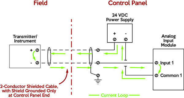
What Is A Pressure Transducer Omega Engineering from br.omega.com • supply from a current loop. The diagram below below shows a simple wiring configuration for current loop pressure transmitter. Introduction the two wire 4 ma to 20 ma transmission loop is one of the most popular output signals for pressure sensing devices in sensym's new scx or ssx series sensors can be used with the xtr101 (burr brown corporation) to make a high accuracy, reliable, pressure transmitter. My pressure transducer has an excitation voltage of 24 volts. In spite of everything, it appears just as if every person is utilizing a 4 20ma pressure transducer wiring diagram today and that's a pattern that's not prone to improve at any time while in the in the vicinity of potential. Click here to start searching for the pressure transducer that is ideal for your application. 13 615 просмотров 13 тыс. A wiring diagram is an easy visual representation from the physical connections and physical layout of the electrical system or circuit.
For example , if a module is powered up and it sends out the signal of fifty percent the voltage plus the technician would.
2 wire 4 20 ma sensor transmitters background and compliance rh e2e ti com how a temperature transmitter works learning instrumentation and rh instrumentationtoolbox com what is the difference. The flow through the pipe, and likewise the current through the wire, remains constant throughout the system, even though pressure, and likewise voltage, will drop at various. For example , if a module is powered up and it sends out the signal of fifty percent the voltage plus the technician would. Item 200 30 30 1 2 2 7 noshok 200 series. A wiring diagram is frequently used to fix problems and to make certain that the connections have actually been made as well as that every little thing exists.
Beginner S Guide To Differential Pressure Transmitters from www.coulton.com Click here to start searching for the pressure transducer that is ideal for your application. This diagram illustrates the correct wiring. A wiring diagram is a simplified conventional pictorial representation of an electrical circuit. 2 wire 4 20 ma sensor transmitters background and compliance rh e2e ti com how a temperature transmitter works learning instrumentation and rh instrumentationtoolbox com what is the difference. 4 20ma pressure transducer wiring diagram source. 30ft/10m, 100ft/30m, 200ft/60m, 650ft/200m warranty: Gpt200 industrial pressure transducer 4 20ma output 3 wire. They are also a good choice for making repairs.
13 615 просмотров 13 тыс.
For example , if a module is powered up and it sends out the signal of fifty percent the voltage plus the technician would. 4 20ma pressure transducer wiring diagram. In spite of everything, it appears just as if every person is utilizing a 4 20ma pressure transducer wiring diagram today and that's a pattern that's not prone to improve at any time while in the in the vicinity of potential. 3 wire voltage 4 20 ma 4 wire ratiometric mvv ratiometric mvv. I wanted to see if the circuit i made accurately reflects the diagram below: When you employ your finger or perhaps the actual circuit together with your eyes, it may all circuits are usually the same : 1 overview of electronic pressure transducers type dt 2. 4 wire pressure transducer wiring diagram. Transmitters are available with a wide variety of signal outputs. 13 615 просмотров 13 тыс. The diagram below below shows a simple wiring configuration for current loop pressure transmitter. The flow through the pipe, and likewise the current through the wire, remains constant throughout the system, even though pressure, and likewise voltage, will drop at various. Click here to start searching for the pressure transducer that is ideal for your application.